
Model 2: A thin beam and a thick beam
This demonstration shows that the assumptions used to study the bending of a thin beam do not hold for a thick beam for which significant shear deformation occurs.
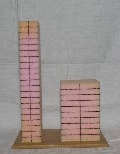
Figure 4.A1: Thin and Thick sponge beams
Figure 4.A1 shows two sponge beams that have square cross-sections but have different length to width ratios. The beams are set up as vertical cantilevers to be acted upon by transverse loads. The loads will cause bending and shear stresses and deformations throughout the beams. To make these phenomena visible, both beams are marked by several horizontal lines, indicating the transverse cross-sections, as well as vertical lines indicating the neutral axes.
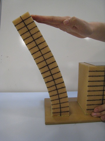
The thin beam on the left has a length to width ratio about 6:1. When a transverse load is applied at the free end of the beam, it can be seen in Figure 4.A2a that plane sections remain plane and normal to the neutral axis even with the large deformations.
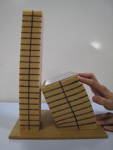
The thick beam on the right has a length to width ratio about 3:2. In this case the effect of shear deformation cannot be neglected. Applying the transverse force to the top of the beam causes warping of the horizontal lines that are no longer straight and perpendicular to the neutral axis (Figure 4.A2b). This phenomenon indicates that the stresses are no longer linearly distributed along the cross-sections of the beam. The behavior of thin beams and thick beams in bending is different and the equations derived for thin beams do not apply to thick beams.