
Post-tensioned plastic beams
This demonstration shows that a beam with profiled post-tension wires is clearly stiffer than the same beam with straight post-tensioned wires.
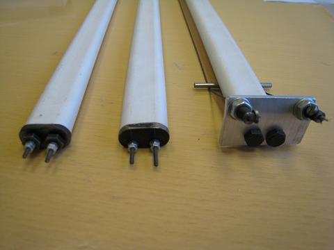
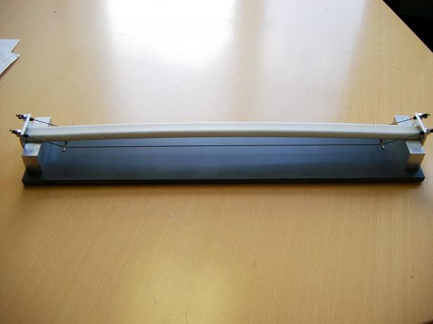
a) Locations of wires from left to right: Models A, B and C b) A plastic beam stiffened by externally profiled wires
Fig: 9-9: Three post-stressed plastic beams with different positions of wires
Three 500mm long plastic tubes are stiffened by a pair of steel wires whose location differs in each tube, see Fig. 9-9:
Model A: The pair of wires is positioned at the neutral plane of the tube.
Model B: The pair of wires is positioned between the neutral plane and the bottom of the tube.
Model C: The pair of wires is placed externally with a profiled shape rather than being straight. Two small metal bars, longer than the width of the tube, are placed underneath the tube to create the desired profile for the wires.
Small metal plates are placed at the ends of the tubes to provide the supports to fix the wires. The wires are fixed into screws and the screws pass through the holes in the end plates and are fixed using nuts. By turning the nuts, the tension in the wires and the forces in the tubes are established. Fig. 9-9a shows the details of the ends of the three tubes and the locations of the wires. Supporting the beams at their two ends gives three post-tensioned simply supported beams shown in Fig. 9-9b. The structural behaviour of the three model beams can be described as follows:
Model A: As the wires are placed in the neutral plane of the tube, the tube itself is in compression and the wires are in tension.
Model B: As the wires are placed under the neutral plane of the tube, the tube is subjected to both compression and bending (bending upwards) and the wires are in tension.
Model C: As shown in Fig. 9-9b, the tensions in the wires provide upward forces through the two diverters to the beam, which will partly balance the downward loads. In other words, the upward forces are equivalent to two spring supports to the beam. Thus Model C is expected to be significantly stiffer than Models A and B.
Positioning the Models in turn on the supports shown in Fig. 9-9b then pressing at the centre of each beam downwards, it can be felt that Model C is obviously stiffer than the Models A and B. The three models all form self-balanced systems, but only Model C has enlarged bending stiffness. A practical example of a stiffened floor using profiled post-tensioned cables will be given in Section 9.4.4.