Zhejiang Dragon Sports Centre (Fig. 9-12)

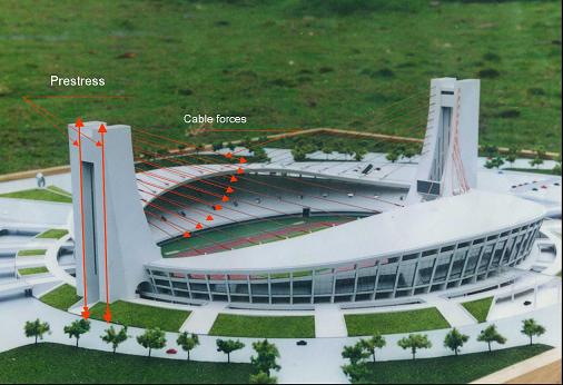
Fig. 9-12: Zhejiang Dragon Sports Centre (Courtesy of Prof. Jida Zhao, China Academy of Buidling Research, China)
The Zhejiang Dragon Sports Centre in China was built in 2000. The stadium has a diameter of 244m and the cantilever roof spans of 50m, creating unobstructed viewing for the spectators. The roof structure adopts double layer lattice shells that are supported by internal and external ring beams. Cables carry the internal ring beams back to the support towers located at two ends of the stadium. The cables are used as elastic supports to the roof, reducing the internal forces (bending moments) and increasing the stiffness of the shell roof.
The towers are subjected to large forces from the cables, which transmit the weight of the cantilever roof and the loads on the roof to the towers. These forces in turn cause large bending moments in the 85m tall cantilever towers. To reduce the bending moments in the towers, post-tension forces were applied to the backs of the towers providing the bending moments opposing the effects of the cables. In this way, the bending moments in the towers become smaller. This leads to a saving of material and a stiffer structure.

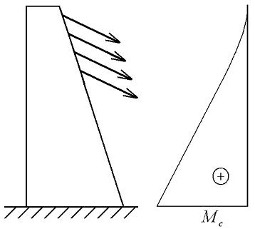
a) Bending moment due to cable forces

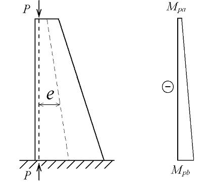
b) Bending moment due to compression forces

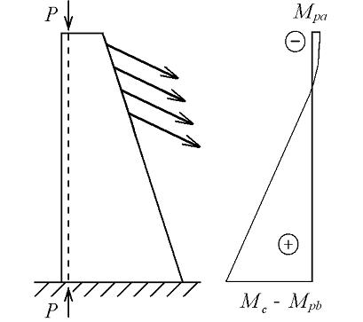
c) Bending moment due to cable forces and compression forces
Fig. 9-13: Illustration of the bending moments in a tower of the Zhejiang Dragon Sports Centre
The bending moments in one of the towers are illustrated in Fig. 9-13. Fig.9-13a shows qualitatively the elevation of the tower and the forces applied on the tower together with the bending moments in the tower. The maximum bending moment occurs at the base of the tower and is noted as ![]() . Fig. 9-13b shows the action of the post-tension forces applied on the tower and the corresponding bending moments. As the distance between the vertical line of action of the compression forces and the neutral axis of the tower varies linearly, the bending moment increases linearly from
. Fig. 9-13b shows the action of the post-tension forces applied on the tower and the corresponding bending moments. As the distance between the vertical line of action of the compression forces and the neutral axis of the tower varies linearly, the bending moment increases linearly from ![]() at the top to
at the top to ![]() at the bottom of the tower, in the opposite direction to those induced by the cable forces. Finally Fig. 9-13c gives the combinations of the two sets of forces on the structure and the resulting bending moments. Thus the bending moments due to the combined forces are
at the bottom of the tower, in the opposite direction to those induced by the cable forces. Finally Fig. 9-13c gives the combinations of the two sets of forces on the structure and the resulting bending moments. Thus the bending moments due to the combined forces are ![]() at the top and
at the top and ![]() at the base. The reduced bending moments due to the action of the post-tensioning of the tower is obvious. According to Eq.9-2, the reduced forces will result in smaller displacements, i.e . a stiffer structure.
at the base. The reduced bending moments due to the action of the post-tensioning of the tower is obvious. According to Eq.9-2, the reduced forces will result in smaller displacements, i.e . a stiffer structure.
