Two rectangular beams and an I-section beam
This demonstration shows how the shapes of cross-sections affect the stiffness of a beam.

The three beams shown in Fig. 3-4 can be made using plastic strips, each with the same amount of material, e.g. three 1mm thick by 15mm wide strips. Fig. 3-4a shows the section of the first beam in which the three strips are glued together to form a section 15mm wide and 3mm deep. The beam shown in Fig. 3-4b is the same as the first beam but its section is turned through 90 degrees. In the beam shown in Fig. 3-4c the three 1mm thick strips are arranged and glued together to form an I section. The second moments of area of the three sections about their horizontal neutral axes are in the ratios: 1 : 25 : 65 (Table 3-1). The stiffnesses of the three beams can be demonstrated and felt through simple experiments as follows:


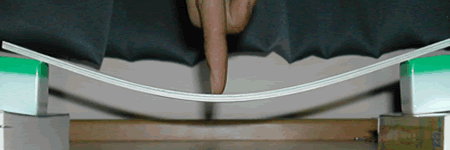
- Support Beam 1 at its two ends, as shown in Fig. 3-5a, and press down at the mid-span of the beam. Notice and feel that the beam sustains a relatively large deflection under the applied load. This beam has a small value of second moment of area because the material of the cross-section is close to its neutral axis.
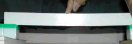
- Replace Beam 1 with Beam 2. Press down at the mid-span of the beam whilst also supporting one end of the beam to prevent its tendency to twist (Fig. 3- 5b). Note that Beam 2 deflects much less than Beam 1 and that its stiffness feels noticeably larger. The material of the cross-section in Beam 2 has been distributed farther away from its neutral axis than was the case for Beam 1, significantly increasing its second moment of area.
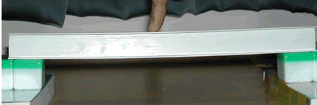
- Replace Beam 2 with Beam 3 and again press down at the mid-span as shown in Fig. 3-5c. The beam is stable and feels even stiffer than the rectangular beam shown in Fig. 3-5b. The increased stiffness is due to the fact that two thirds of the material of the cross section is placed in the flanges, i.e. as far away as possible from the neutral axis of the section.
The simple demonstration shows that the I-section Beam 3 is significantly stiffer than the other two beams and that Beam 2 is much stiffer than Beam 1, although all use the same amount of material.
