
Buckling loads and boundary conditions
This model demonstrates qualitatively and quantitatively the relationships between the critical loads and boundary conditions of a column (Eq. 10-3) and the corresponding buckling shapes.
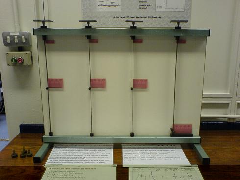
a) Four columns with different boundary conditions b) Critical loads and buckling shapes
Fig. 10-6: Critical loads, buckling shapes and boundary conditions of columns
The model shown in Fig. 10-6 contains four columns with the same cross-section but each with different boundary conditions; (from left to right and from bottom to top), pinned-pinned, fixed-fixed, pinned-fixed and free-fixed. The model has load platens on the tops of the columns which allow weights to be added and applied to the columns. This model can demonstrate the different buckling or critical loads of the columns and the associated buckling shapes or modes.
- The different boundary conditions should be observed by the user before applying loads to the columns. (Fig. 10-6a)
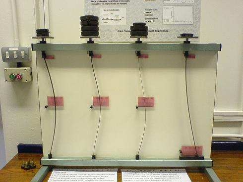
- Weights are added incrementally to the platens until the columns buckle (Fig. 10-6b) at which time the loads, including the weights and the platens, are the critical loads of the columns and the shapes of the columns are the buckling modes.
- With all columns loaded (Figure 10.6b), the relative buckling loads and buckling modes can be observed and compared for the different boundary conditions. Table 10-2 gives the measured critical loads of the four columns.
Table 10-2: Comparison of buckling loads of a column with different boundary conditions
Boundary conditions |
Pinned-Pinned |
Fixed-fixed |
Fixed-pinned |
Fixed-free |
Critical load |
|
|
|
|
Relative critical load |
1 |
4 |
2.05 |
0.25 |
Test critical load ( N ) |
5.61 |
20.8 |
13.0 |
4.05 |
Relative test critical load |
1 |
3.71 |
2.31 |
0.72 |
It is to be expected that there will be some differences between the predicted and the test critical loads, but significant error occurs in the fixed-free model (Table10-2). Several trials showed that the free-end at the bottom of the strut was not really free to move laterally due to small amount of friction. In addition, the column is shorter than the others, which can be seen in Fig. 10-6a. Real structures rarely behave in exactly the same manner as the theoretical models.