
Centre of mass and stability
This demonstration shows how the stability of a body relates to the location of its centre of mass and the size of its base.
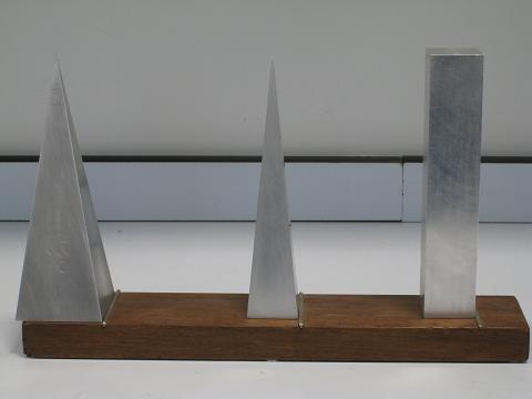
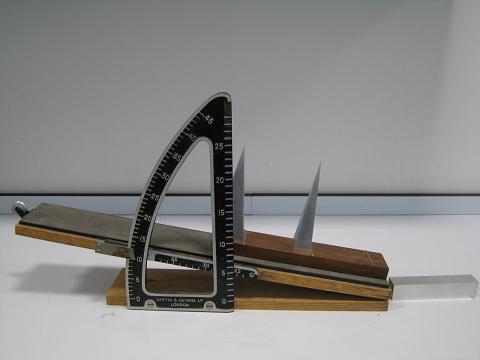
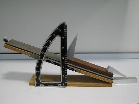
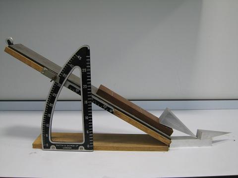
Fig. 2-9a shows three aluminum blocks with the same height of 150mm. The square sectioned block and the smaller pyramid have the same base area of 29mm x 29mm. The larger pyramid has a base area of 50mm x 50mm but has the same volume as that of the square sectioned block. The three blocks are placed on a board with metal stoppers provided to prevent sliding between the base of the blocks and the board when the board is inclined. As the board is inclined, its angle of inclination can be measured by the simple equipment shown in Fig. 2-9b. Basic data for the three blocks and the theoretical critical angles calculated using Eq. 2-7 are given in Table 2-1. Theory predicts that the largest critical angle occurs with the large pyramid and the smallest critical angle occurs with the square sectioned block.
The demonstration is as follows:
- The blocks are placed on the board as shown in Fig. 2-9 in the order of increasing predicted critical angle.
- The left hand end of the board is gradually lifted and the square sectioned block is the first to become unstable and topple over (Fig. 2-9b). The angle at which the block topples over is noted.
- The board is inclined further and the pyramid with the smaller base is the next to topple (Fig. 2-9c). Although the height of the centre of mass of the two pyramids is the same, the smaller pyramid has a smaller base and the line of action of its weight lies outside the base at a lower inclination than is the case for the larger pyramid. The angle at which the smaller pyramid topples over is noted.
- As the board is inclined further the larger pyramid will eventually topple over but its improved stability over the other two blocks is apparent (Fig. 2-9d). Once again the angle at which the block topples is noted.
The angles at which the three blocks toppled are shown in Table 2.1.
Table 2.1 Comparison of the calculated and measured critical angles
Model |
Cuboid |
Small Pyramid |
Large Pyramid |
Height of the model (mm) |
150 |
150 |
150 |
Height of the centre of mass (mm) |
75.0 |
37.5 |
37.5 |
Width of the base (mm) |
29 |
29 |
50 |
Volume ( |
|
|
|
Theoretical Max Inclination (deg.) |
10.9 |
21.9 |
33.7 |
Measured Max Inclination (deg.) |
10.0 |
19.0 |
31.0 |
The results of the demonstration as given in Table 2.1 show that:
- The order in which the blocks topple is as predicted by Equation 2.7 in terms of the measured inclinations and confirms that the larger the base or the lower the centre of mass of a block, the larger the critical angle that is needed to cause the block to topple.
- All the measured critical angles are slightly smaller than those predicted by Eq. 2-7.
Repeating the experiment several times confirms the measurements and it can be observed that the bases of the blocks just leave the supporting surface immediately before they topple, which makes the centres of the masses move outwards. In the theory the bases of the blocks remain in contact with the support surface before they topple.
This demonstration shows that the larger the base and/or the lower the centre of gravity, the larger will be the critical angle needed to cause the block to topple and that this angle is slightly less than that predicted by theory.