
The bending moment at one fixed end of a beam
This demonstration shows how the end moment in a fixed beam can be measured.
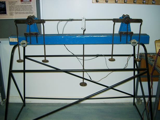
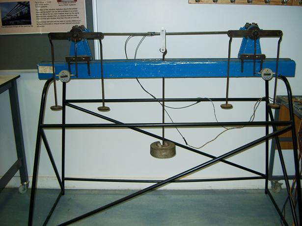
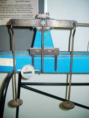
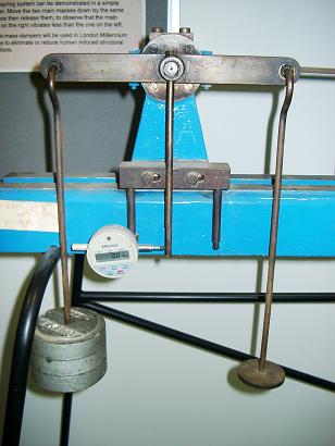
Fig. 7-5: Bending moments at the fixed ends of a uniform beam
At the fixed end of a beam, both the displacement and the rotation, or slope, are zero. Using the condition that the slope at a fixed end equals zero, a fixed end condition can be created and the moment associated with this condition can be determined.
Fig. 7-5a shows a simply supported beam with a supporting frame. A hanger is placed at the centre of the beam so loads can be added. The ends of two vertical arms at the supports are attached to displacement gauges. Readings from the gauges divided by the lengths of the arms are the end rotations of the beam. If weights are placed on two end hangers, they will induce rotations in the opposite directions to those induced by the load applied at the centre of the beam. When the readings in the gauges are reduced to zero, a beam with two fixed ends has been created and the fixed end moments are the products of the weights on the hanger and the horizontal distances between the ends of the hangers and the supports.
Fig. 7-5b shows a mass of 5 kg placed on the hanger at the centre of the beam and Fig. 7-5c shows the rotation of the beam at the left support and the reading of 2.99 mm. By adding a mass of 3 kg at to each of the two end hangers (Fig. 7-5d), the gauge at the left end shows a reading of 0.01 mm, indicating that a fixed boundary condition has been created. The associated fixed end moment is 3x9.81x0.125 (the distance between the end hanger and the support) = 3.68 N.m in this case.