
Model 4: Lateral stiffness of vertical members
This model compares the relative stiffness of a cantilever and the stiffness of a beam with both ends clamped and investigates apparent errors in the demonstration.
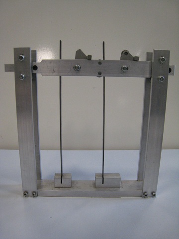
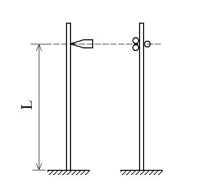
Figure 7.A1
The model is shown in Figure 7.A1a. Two pairs of vertical aluminum members are rigidly connected to the base member. Two identical steel strips are placed vertically and clamped at their base. A horizontal member is located at upper part of and between the vertical members. This can move in the horizontal direction along the guides of ball bearings. There are two elements in the middle of the horizontal member which can be flapped down independently to form the loading points and the boundary conditions shown in Figure 7.A1b. A mechanical force gauge is used to apply and read the horizontal force on the right end of the horizontal member.
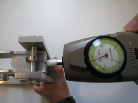
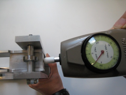
Figure 7.A2: The readings of the loads on the two columns
Figure 7.A2 shows the readings when the forces are applied to the cantilever and the beam with the fixed top end. For the cantilever the gauge reads about 4 x 0.25 x 9.81 = 10 N and for the fixed beam it reads about 12 x 0.25 x 9.81 = 30 N. In other words, the lateral stiffness of the fixed beam is about 3 times that of the cantilever. However, the theory of beams predicts a ratio of stiffness of 4 [7.3]. What is wrong?
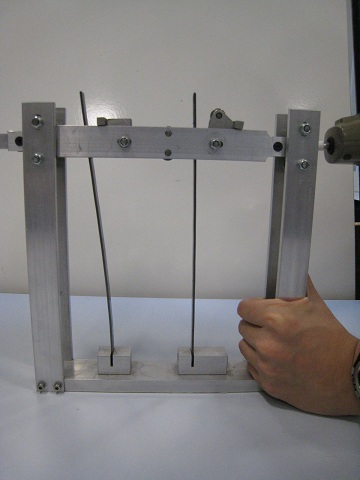
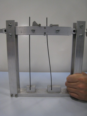
Figure 7.A3: Deformations of the two members
Figure 7.A3 shows the deformed shapes of the two vertical members subjected to the above loading. It can be observed that the fixed boundary condition is effectively not fully realized as some rotation occurs at the top end of the apparently fixed beam. This is due to the design of the device as indicated on the right part in Figure 7.A1b – the three roller fixings do not form a true fixed boundary condition and hence the stiffness of the member is not that of one with true fixed end.