
Direct and zigzag force paths
This model demonstration allows one to feel the relative stiffensses of two similar plastic frames and shows the effect of internal force paths.
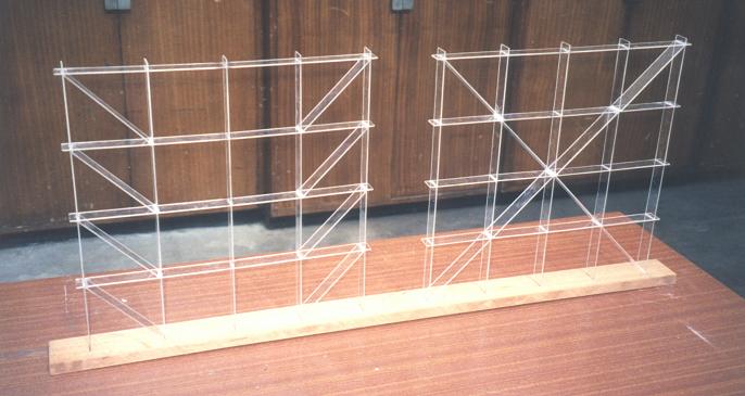
Fig. 8-7: Braced frame models showing direct and zigzag force paths
In order to ‘feel’ the effect of the force paths, two frames were made of plastic, with the same overall dimensions 400 mm by 400 mm and member sizes of 25 mm by 2 mm, see Fig. 8-7 [8.7]. The only difference between the two frames is the arrangement of bracing members. The forms of the two frame models are the same as the example calculated in section 8.2.3 and the test Frames A and B in Section 8.3.1. The relative stiffnesses of the two frames can be felt by pushing a top corner joint of each frame horizontally. The frame on the right side feels much stiffer than the one on the left. In fact, the stiffness of the right frame is about four times that of the left frame. The load applied to the right frame is transmitted to its supports through a direct force path while for the frame on the left, the force path is zigzag.