
Experimental Verification
These simple experiments verify the concept that the more direct the internal force paths, the stiffer the structure, and the first three corresponding criteria.
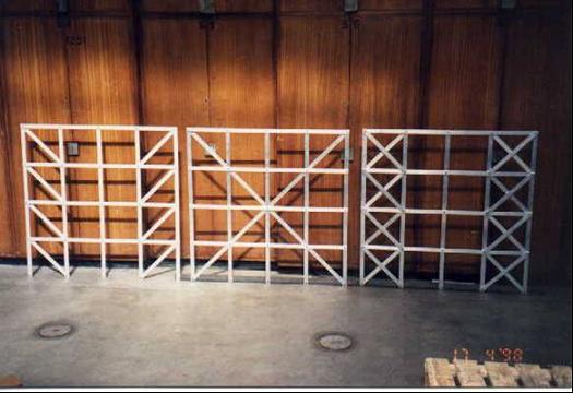
Fig. 8-5: Aluminium test frames (Frames A, B and C are placed from the left to right)
Three aluminium frames were constructed with the same overall dimensions of 1025 mm by 1025 mm. All members of the frames have the same cross-section of 25 mm by 3 mm. The only difference between the three frames is the arrangement of the bracing members as shown in Fig. 8-3. It can be seen from Fig. 8-5 that
a) Frame A is traditionally braced with eight members, which satisfies the first criterion.
b) Eight bracing members are again used in Frame B but are arranged to satisfy the first three criteria.
c) A second traditional bracing pattern is used for Frame C with sixteen bracing members arranged satisfying the first two criteria.
The three frames were tested using a simple arrangement. The frames were fixed at their supports and a hydraulic jack was used to apply a horizontal force at the top right-hand joint of the frame. A micrometer gauge was used to measure the horizontal displacement at the top left-hand joint of the frame. A lateral restraint system was provided to prevent out-of-plane deformations [8.7].
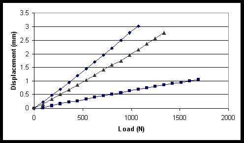
Fig. 8-6: Load-deflection curves for Frames A, B and C
The horizontal load-deflection characteristics of the three frames are shown in Fig. 8-6. It can be seen that the displacements of Frame B, which satisfied the first three criteria, are about a quarter of those of Frame A for the same load. Frame C with eight more members but not satisfying the third criteria is obviously less stiff than Frame B. For example, the displacements corresponding to the load of about 1070N are 3.0mm for Frame A, 0.73mm for Frame B and 2.2mm for Frame C respectively. The experiment results for Frame A and Frame B align with the conclusions obtained in Example 8-1.