
Model 6: Shear centre of a thin-walled open section
This demonstration shows the location of the shear centre of a thin-walled open section. When a vertical force is applied through the shear centre of the section, no twisting or torsion occurs.
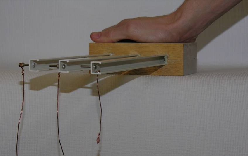
Figure 5.A1: Different loading positions of three identical cantilever beams with open sections
Figure 5.A1 shows three identical plastic beams with channel cross sections. The shear centre of a cross-section can be identified by the definition of the shear centre. A different loading position for each beam is selected. From left to right, the loading positions are to the left of the shear centre, at the shear centre and to the right of the shear centre. Loads can be applied by pulling bronze wires attached to the loading points.
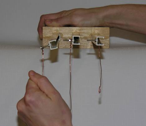
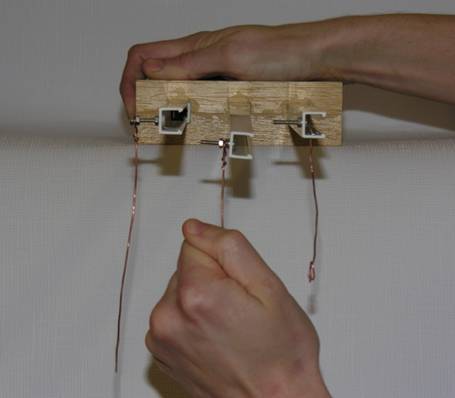
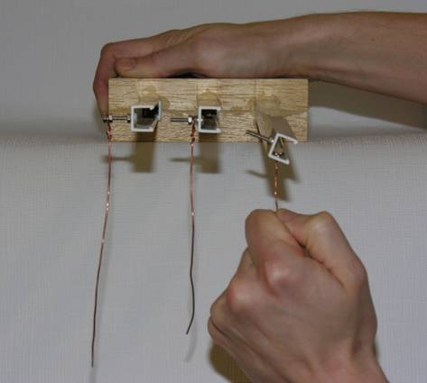
Figure 5.A2: Deformation of the beams due to vertical loads
Figure 5.A2 shows the responses of the three cantilevers to the applied loads. It can be observed from Figure 5.A2 that:
- The beam is twisted in the anti-clockwise direction when the load is applied to the left of the shear centre.
- The beam deforms vertically without twisting when the load is applied through the shear centre of the section.
- The beam is twisted in the clockwise direction when the load is applied to the right of the shear centre.