
Effect of torsion
This demonstration shows the effect of shear stress in a non-circular section member induced by torsion.
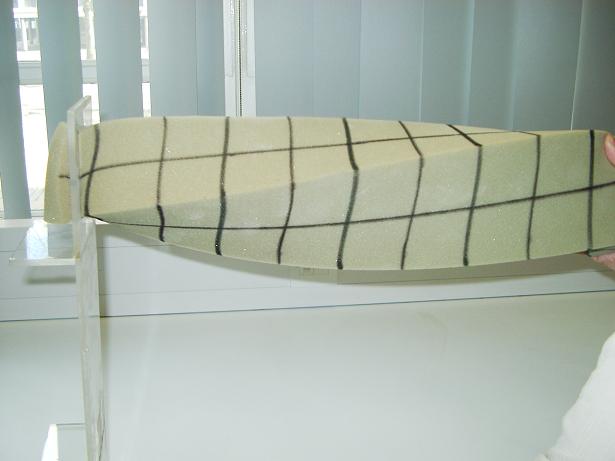
Take a length of sponge of rectangular cross section and mark longitudinal lines down the centre of each face. Then add perpendicular lines at regular intervals along the length of the sponge. Restrain one end of the sponge in a plastic frame as shown in Fig. 5.5 and twist the other end. It can be observed that:
- The lines defining the cross sections of the beam are no longer straight.
- The angles between the horizontal longitudinal lines, which define the neutral axis, and the vertical lines are no longer 90 degrees.
These observations are different from those of the beam in bending, see Section 4.3.1.